

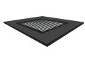

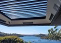
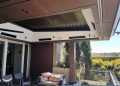
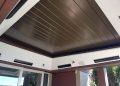
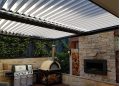
Infinity Reveal DIY Motorised Louvred Roof
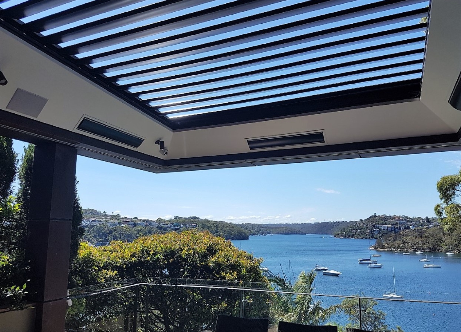
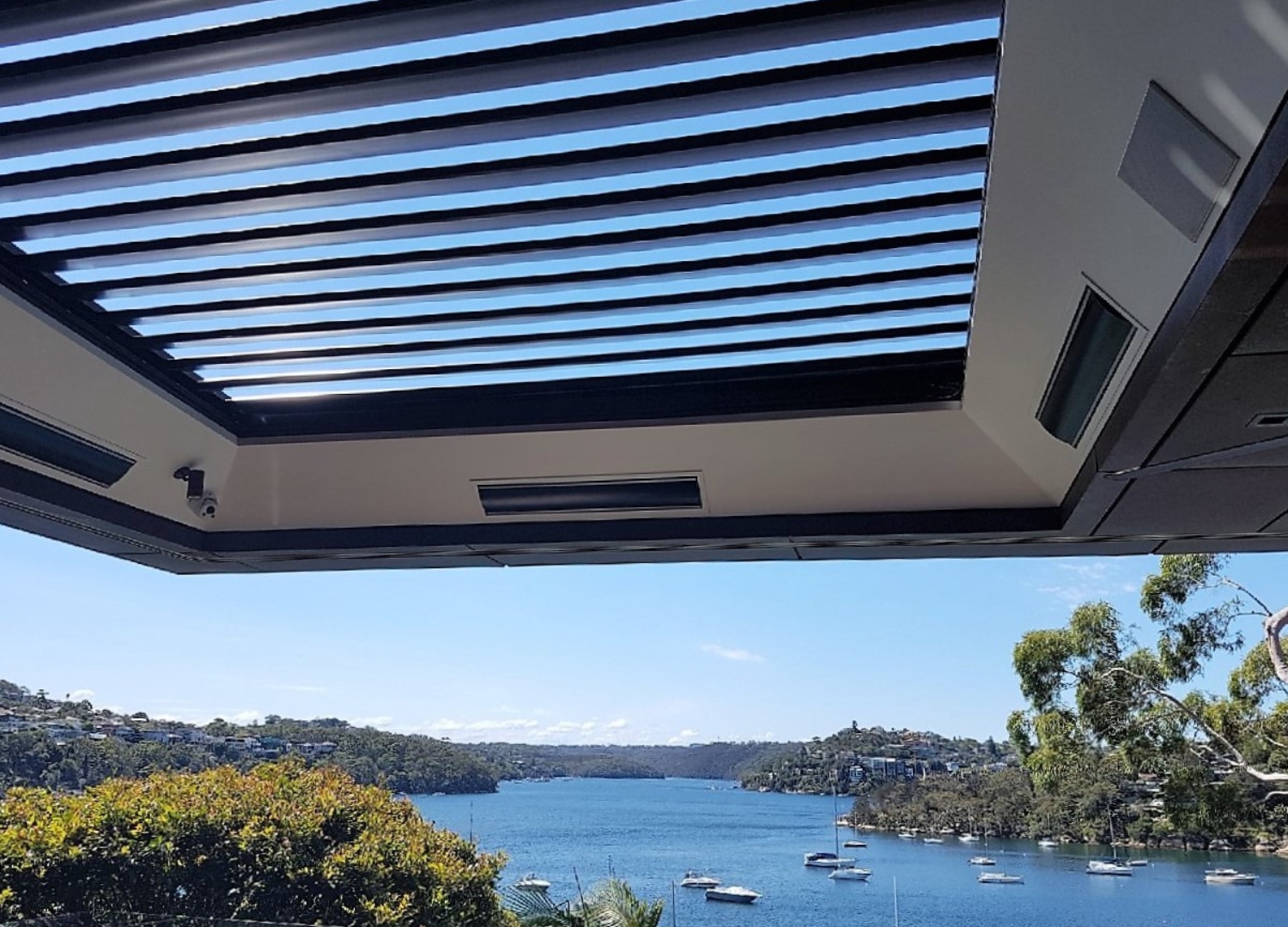
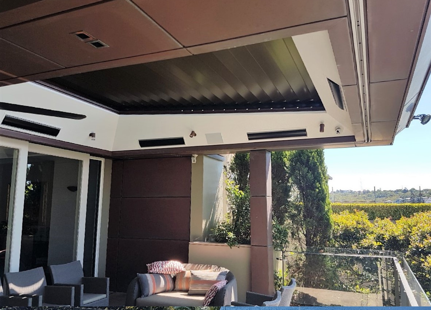
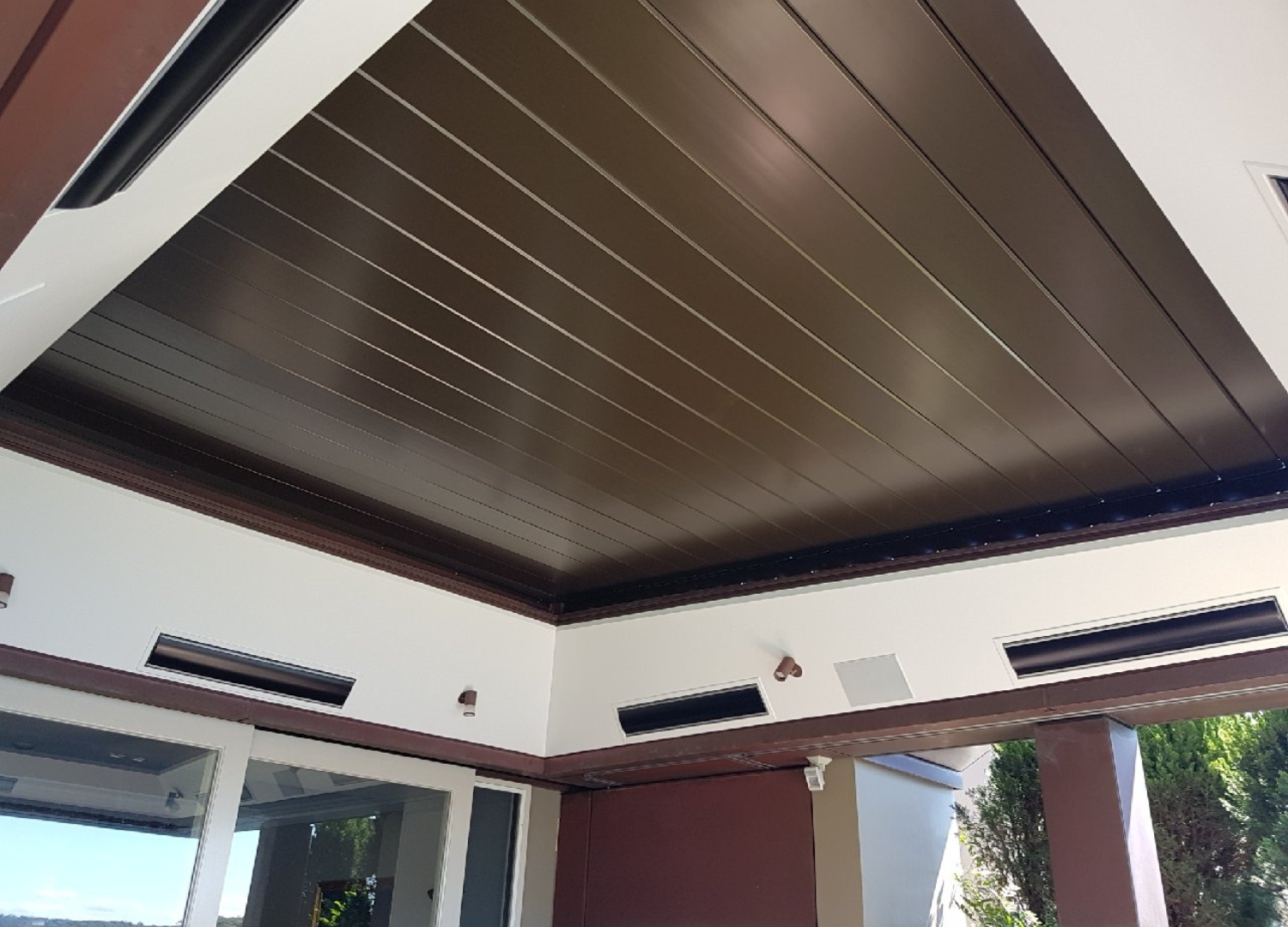
Enhance your outdoor living with the Infinity Reveal DIY Motorised Louvred Roof. This fully customisable system lets you effortlessly control light and shade with sleek, motorised louvres for any patio, deck, garden, or custom pergola.
With just a button push, this creative design offers a smooth transition between areas that receive natural light and those that are shaded or shielded. For any patio, deck, or garden area, the sleek Infinity Reveal aesthetic offers a contemporary and attractive finish, making it an ideal solution for opening roof pergolas, motorised pergolas, and modern outdoor living spaces. The simple DIY installation guarantees a hassle-free setup.
For a compact alternative, explore the Single Post DIY Motorised Louvred Roof — perfect for smaller outdoor spaces. You can also discover more premium shading solutions at Vivid Retractable Roof to complement your modern outdoor setup and louvred pergola design.
 |
 |
Product successfully added to the Quote List
Total Price Including Addons:
$4,757.45
Need Help? Give us a call
Be the first to review “Infinity Reveal DIY Motorised Louvred Roof”

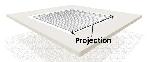
Max Blade Span – 4500mm
Refer to the Roof Configuration Tab for the exact wind class span.
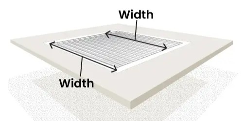
Max Beam Span between Posts – 6000mm
Refer to the Roof Configuration Tab for the exact wind class span.
Standard Colours
Custom Colourbond Colours are available on request.
Please note that these colours are Dulux Powder Coated colour matches. There may be a slight colour variation from the Dulux colour swatch. Please refer to the colour swatches supplied by Louvred Roof Online.

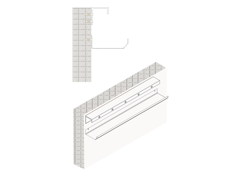
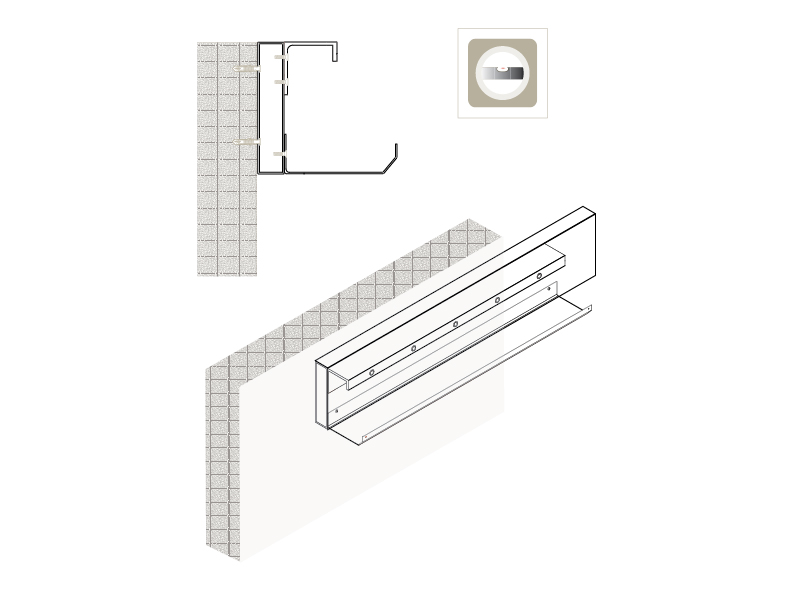
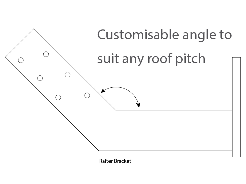
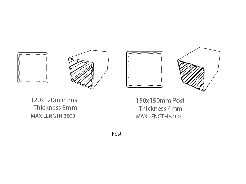
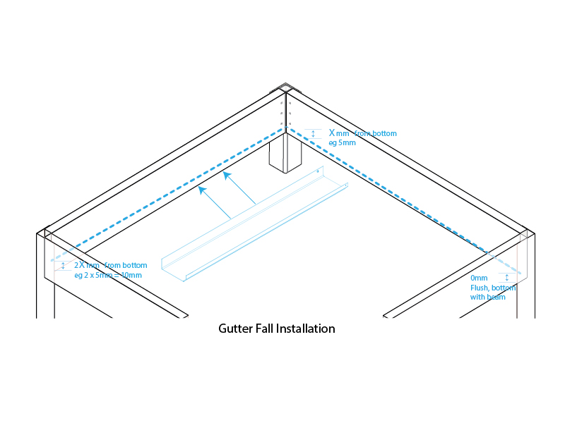
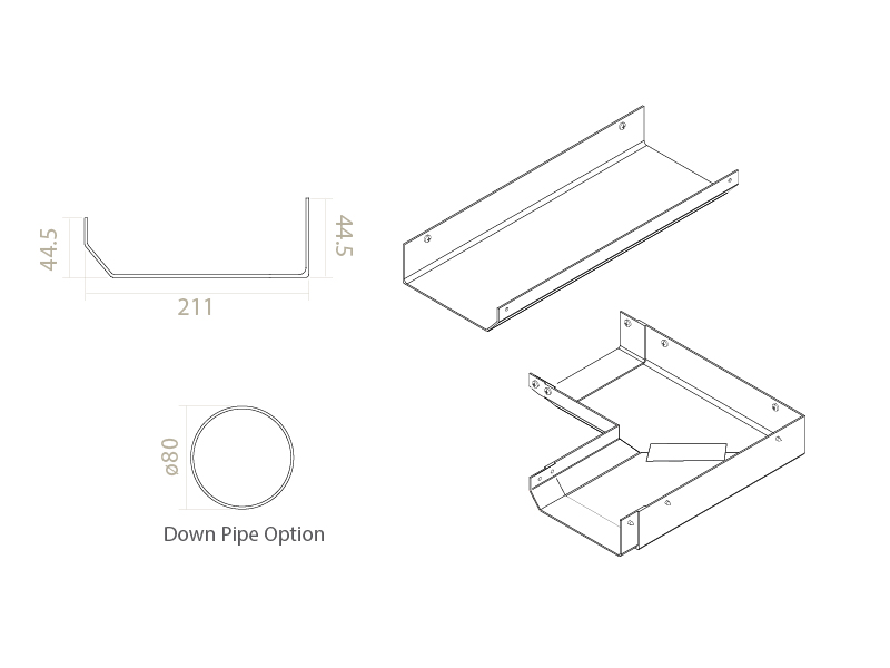
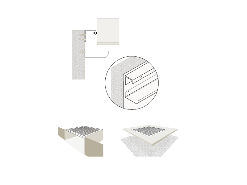

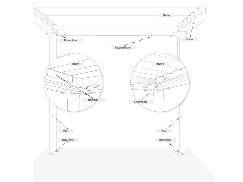



Step – 1
Layout the Site. Marking where the 4 corners of the roof will be positioned.
Step – 2
Check the level of the site. Cut your posts according to the level of the site and then mark wall level with the post.

Step – 3
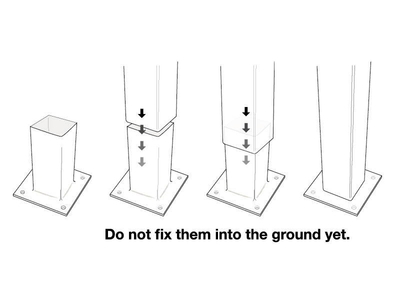
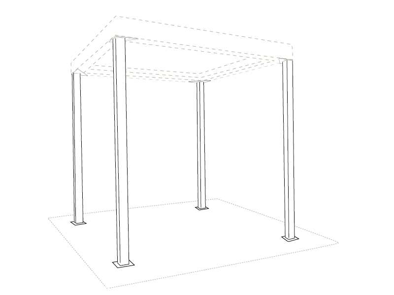
Base Plate: Place the 4 post in position, hold them up with props. Do not fix them into the ground yet.
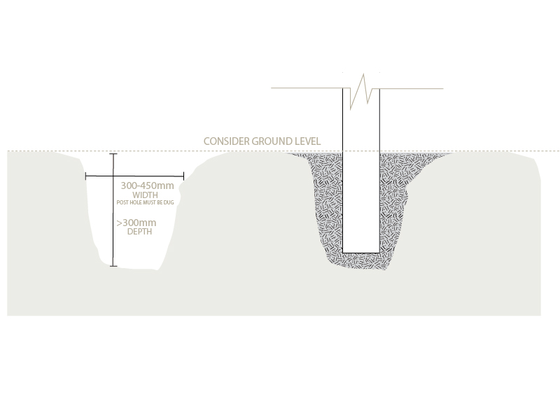
Post Footing: Dig footings at the required depht, and concrete the posts into place. making sure all posts are level at the top.
The following instructions apply for free standing structures. If you are wall mounting please mount to the wall as shown below and follow the instructions accordingly.
Step – 4
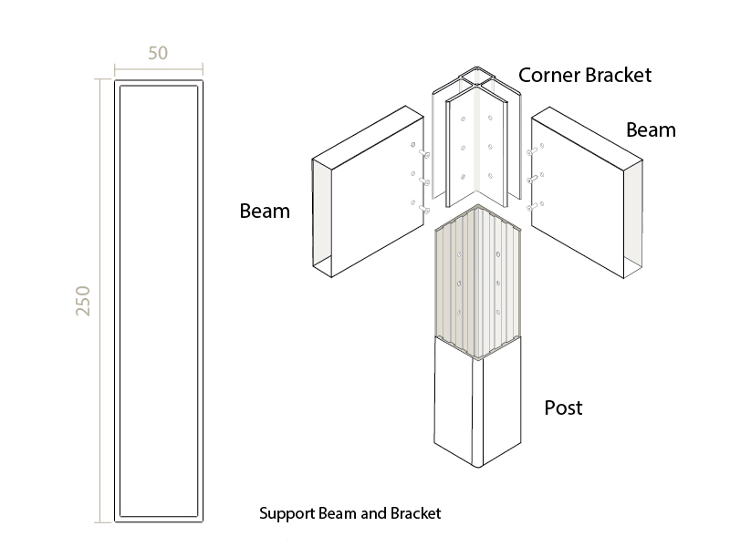
Fix the corner joiners into the top of the 250×50 Surrrounds, Using the Stainless steel M8x30mm Hex Bolts supplied. Only fix one of corner joiners itno each 250×50 Surround.
Step – 5
Position the first 250×50 Beam on top of the posts. Loosely fixing it to the post mounting plate.
Step – 6
Slide the next 250×50 Beam into the corner joiner of the previous 250×50 beam. Fix the corner into position, ensuring the corner is square.
Step – 7
Repeat this process for the 2 other 250×50 beams.
Please Note: When fixing directly to a wall or existing structure. Start at the wall first and work your way out to the posts.

Step – 8
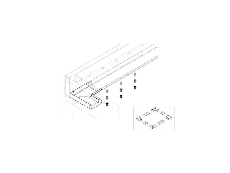
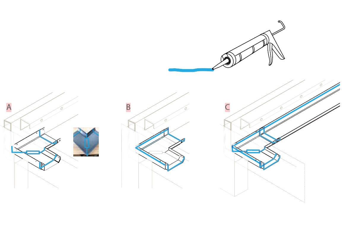
Gutter Installation: First the corner gutters into position, using the Phillips Pan Head St4.8*13 self-tapping screws supplied.
Step – 9
Silicone: Before fixing the corner apply Sikaflex (silicon) or similar to the beam to ensure the joint is completely water tight.
Step – 10
Gutter Installation: Slide the gutters up into the corners joints, applying Sikafex at the joints, and along the edge of the beam and gutter joint. Fix the gutters to the beam using the stainless steel pan head self-tapping screws supplied.

Step – 11
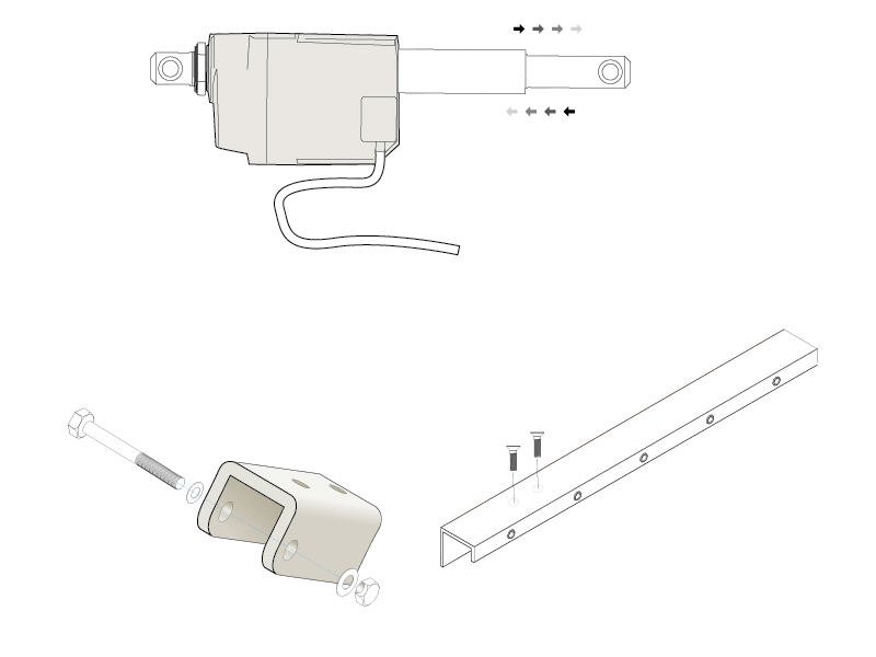
Motor Installation: Attach the motor mount on the Side Rail, using the hex bolts supplied.

Step – 12
Motor Installation: Attach the Motor to the Motor Mount ( U channel Bracket ) with pin. Secure with nut amd bolt.

Step – 13
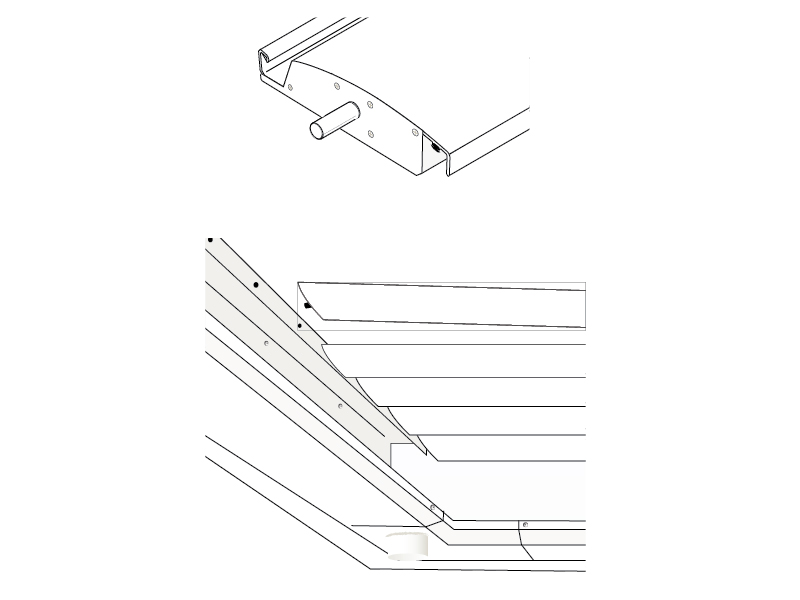
Motor Installation: Attach the control rod bracket to the control bar using nuts and bolts supplied. Slide motor arm over shaft on the control rod bracket and secure with Circlip.
Step – 14
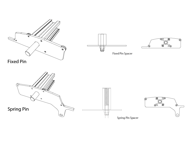
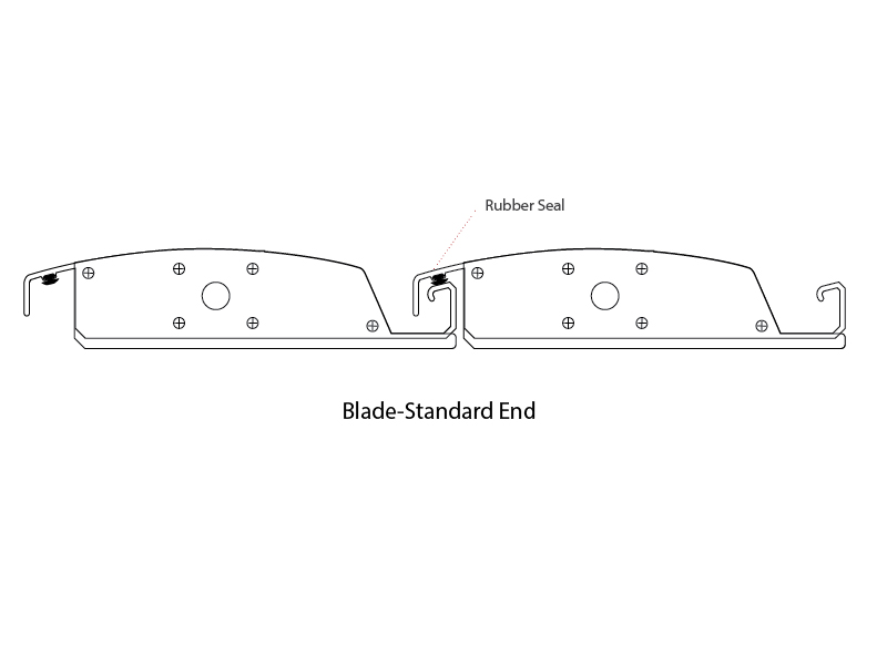
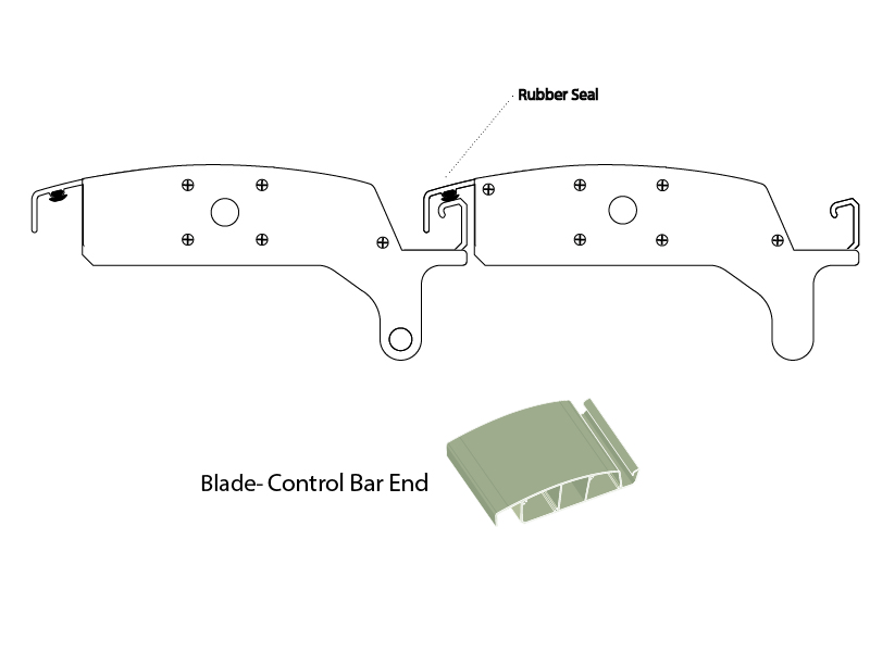
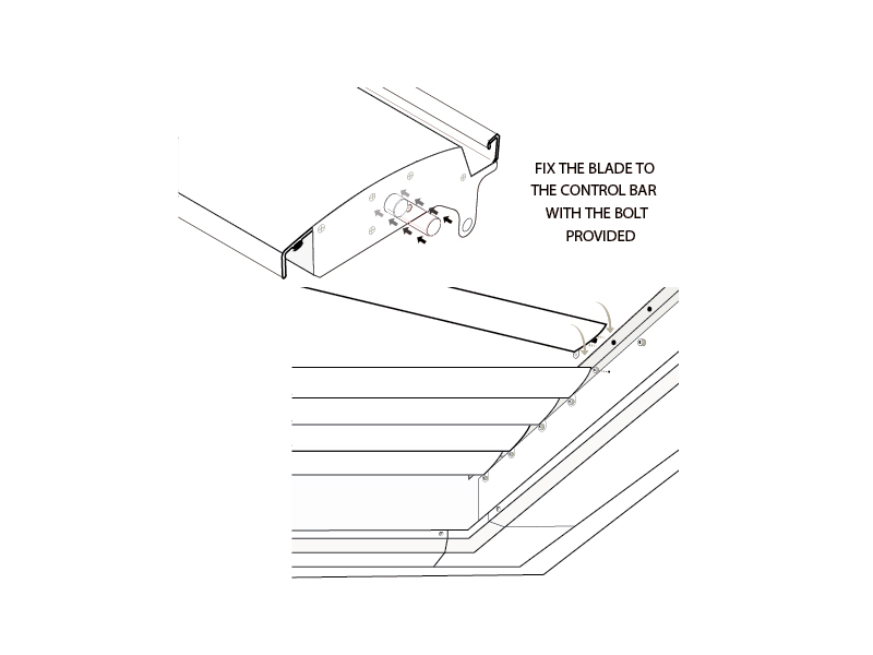
Blade Installation: Mount the blades, by sliding the ‘fixed pin’ in the idle side and the ‘spring pin’ in the motor side. Fix the blade to the control bar with the bolt provided (M8*20).
Step – 15
Half Blade Installation: If a half blade is supplied, lift it into position using the predrilled holes in the beam & L-angle as a guide. Rivet in place using rivets supplied. The fall of the half blade should align with the fall of the operable blades.
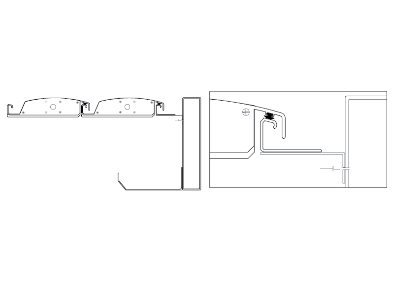
| Wind Class | Ultimate Limit State (m/s) | Serviceability Limit State (m/s) | Wu (kPa) | Ws (kPa) | Maximum Allowable Span (mm) | Screw spacing (mm) Side Stile to Beam |
|---|---|---|---|---|---|---|
| N1 | 34 | 26 | 0.69 | 0.41 | 5000 | 100 |
| N2 | 40 | 26 | 0.96 | 0.41 | 5000 | 100 |
| N3 | 50 | 32 | 1.50 | 0.61 | 4300 | 75 |
| N4 | 61 | 39 | 2.23 | 0.91 | 3500 | 75 |
| N5 | 74 | 47 | 3.29 | 1.33 | 2900 | 50 |
| N6 | 86 | 55 | 4.44 | 1.82 | 2500 | 50 |
| Wind Class | Ultimate Limit State (m/s) | Serviceability Limit State (m/s) | Wu (kPa) | Ws (kPa) | Supported Lourve Span (mm) | Maximum Allowable Span (mm) | Number of Fasteners from beam to post |
|---|---|---|---|---|---|---|---|
| N1 | 34 | 26 | 0.69 | 0.41 | 5000 | 5000 | 3 |
| N2 | 40 | 26 | 0.96 | 0.41 | 5000 | 4300 | 3 |
| N3 | 50 | 32 | 1.50 | 0.61 | 4300 | 3600 | 4 |
| N4 | 61 | 39 | 2.23 | 0.91 | 3500 | 3300 | 4 |
| N5 | 74 | 47 | 3.29 | 1.33 | 2900 | 3000 | 5 |
| N6 | 86 | 55 | 4.44 | 1.82 | 2500 | 2700 | 5 |
| Supported Lourve Span (mm) | Maximum Allowable Span (mm) | Number of Fasteners from beam to post | Supported Louvre Span (mm) | Maximum Allowable Span (mm) | Number of Fasteners from beam to post |
|---|---|---|---|---|---|
| 4500 | 5400 | 3 | 3500 | 6000 | 2 |
| 4000 | 4800 | 3 | 3000 | 5500 | 3 |
| 3500 | 4000 | 4 | 2500 | 4800 | 3 |
| 3000 | 3500 | 4 | 2000 | 4300 | 3 |
| 2500 | 3200 | 5 | 1500 | 4100 | 4 |
| 2000 | 3000 | 5 | 1000 | 4000 | 4 |

Reviews
There are no reviews yet.